
PCB 패널화 가이드: 레일, 브레이크어웨이 탭, 기준 마크 및 조립 트레이드오프
SUNTOP Electronics
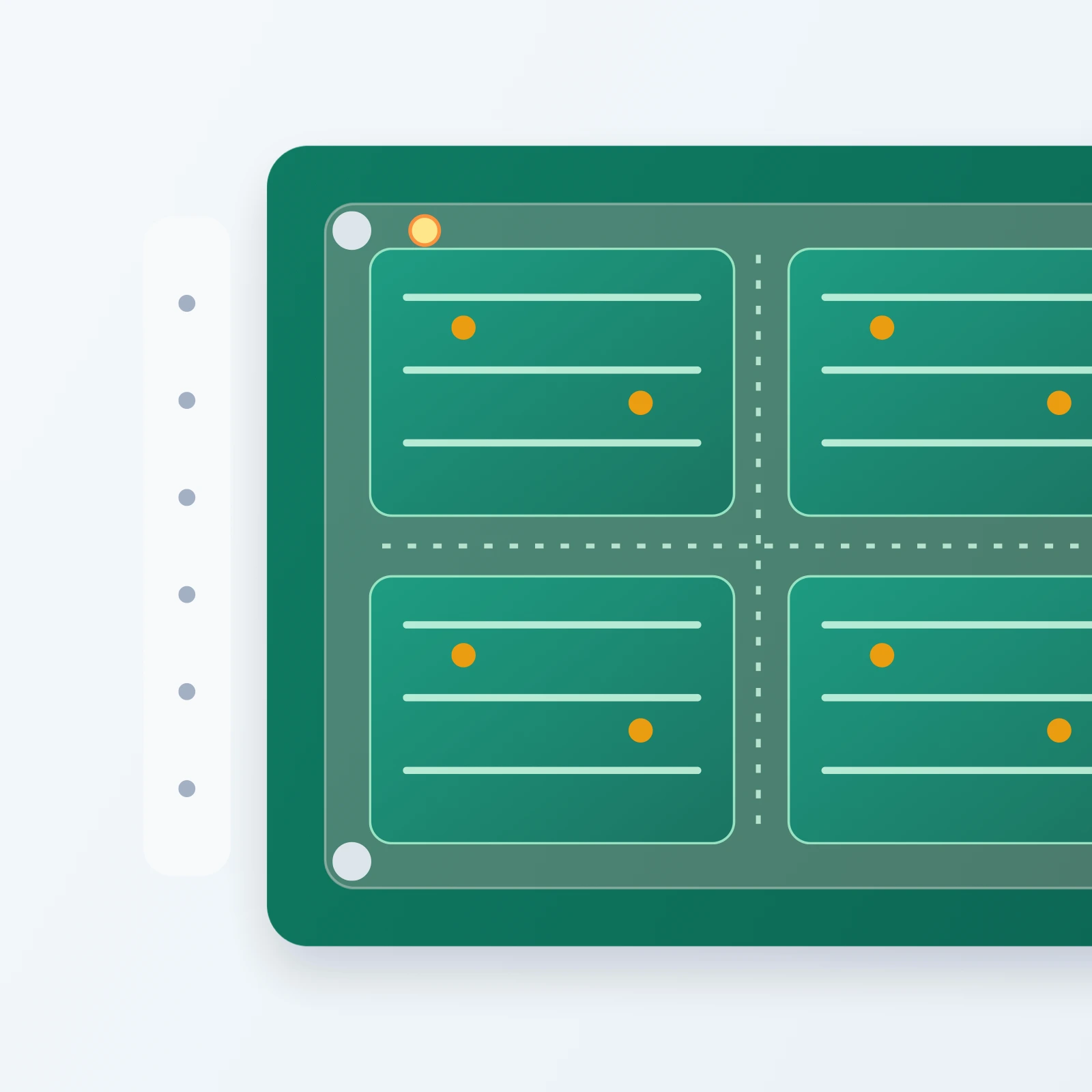
A good PCB panelization guide helps teams answer a practical question before sending files: how should boards be arranged, supported, and separated so fabrication and assembly run with less risk?
Many delays in prototype and low-volume production do not come from the circuit itself. They come from incomplete panel decisions. A weak panelization approach usually shows up as quote questions about rails, array spacing, breakaway method, fiducials, tooling holes, or whether the factory should redesign the panel from scratch.
What a PCB Panelization Guide Should Help You Decide Before Manufacturing
A useful panelization approach is not only about fitting more boards onto a panel. It should help you decide whether the panel supports the full build flow: printing, placement, reflow, inspection, depanelization, and later handling.
In practice, it should clarify:
- whether the supplier should build from a single-board file or from a defined array
- whether rails are needed for conveyor stability or fiducial placement
- how boards will separate after assembly
- what keepout is needed near breakaway features
- what support features the SMT line expects to see
General references such as the IPC standards overview and the definition of a fiducial mark help with terminology, but your production-ready plan still needs to reflect actual board shape, component density, and assembly route.
Core Panel Frame and Board Array Decisions to Review Early
Start with board count per panel. More boards per panel can improve material usage, but only if the resulting array remains stable through printing, placement, and depanelization.
Next, review rail strategy. Outer rails are often needed to carry tooling holes, fiducials, and conveyor support. If the individual board outline is irregular, the rail decision becomes even more important. A practical guide should also check spacing between units, clearance near board edges, and whether components overhang the board boundary.
You should also decide whether the array is intended for prototype flexibility or repeatable production. If your project needs help aligning PCB fabrication and assembly assumptions, review the package with the broader manufacturing services team before release instead of treating panel layout as a last-minute CAM task.
How Breakaway Tabs, V-Score, and Depanelization Choices Affect Assembly
Every solid panelization plan needs a section on how boards will separate after assembly, because depanelization risk often appears only after the first build.
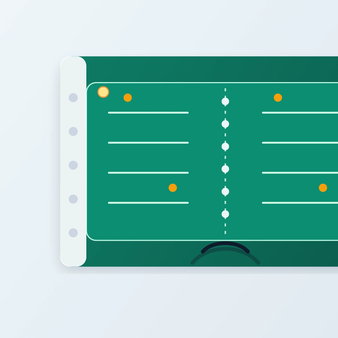
This close-up highlights how panel rails, breakaway tabs, perforation lanes, fiducials, and tooling features need clearance before the board is separated after assembly.
Tab-route panelization gives designers flexibility for irregular outlines, but the tab locations must respect copper, edge components, and mechanical stress points. Mouse-bite perforations also need enough clearance so depanelization does not damage pads, crack ceramic parts, or leave unacceptable edge finish.
V-score panelization can simplify separation for straight board edges, but it works best when the board geometry suits scoring and when components are kept away from the scored lines.
A realistic plan should therefore review:
- which separation method matches the board outline
- how close copper and components sit to the breakaway edge
- whether manual or fixture-based depanelization is expected
- whether edge roughness after separation is acceptable for the product
- whether panel strength remains adequate before the boards are separated
Fiducials, Tooling Holes, and Support Features That Improve Assembly Stability
Global fiducials help the placement system locate the panel accurately. Tooling holes support repeatable alignment in printing and assembly fixtures. On thinner boards or uneven arrays, extra support strategy may also be needed so the panel does not flex excessively during SMT processing.
A careful plan should make these details visible early rather than assuming the supplier will add them without tradeoffs. When rails are too narrow, fiducials may end up too close to board features. When support features are missing, the panel may become harder to print and inspect consistently.
Common Panelization Mistakes That Slow Quotes or Create Yield Risk
One common mistake is leaving panelization undefined while still expecting an accurate assembly quote. If the factory has to guess the array strategy, the quote may be delayed or based on assumptions that later change.
Another mistake is placing components too close to tabs, scored edges, or rail removal zones. The board may look fine in layout, but the actual separation process can stress the finished assembly.
A third mistake is treating panel utilization as the only goal. Saving material is useful, but ignoring handling stability, fiducial access, or depanelization practicality usually creates more downstream cost than it saves.
Finally, some teams send a single-board package and mention panel needs only in email. If panel intent matters to cost, yield, or fixture design, it should be stated inside the release package.
How to Hand Off Panelization Requirements to Your PCB Assembly Partner
Before release, make sure the manufacturing partner can see:
- whether a specific array is required or proposed
- preferred breakaway method
- component keepout expectations near panel edges
- fiducial and tooling-hole intent
- any handling or depanelization concerns tied to fragile parts or odd board shape
- whether the factory may optimize the array after review
If you are not fully certain that your proposed array matches the actual production method, say that clearly and invite review. That is much better than freezing a weak panel definition too early.
For teams preparing a prototype or production RFQ, the safest route is to hand off the design package and ask the supplier to confirm manufacturability before build release. You can also contact the PCBAssemblyMFG team with the board context before final quoting.
A practical panelization plan does not need to be long. It needs to make the array strategy, depanelization method, and assembly assumptions clear enough that the factory can review the board without guesswork.